2 👮 Air Law
ICAO states. EU law. National law.
2.1 Licensing
You need a license to fly as a crew member in any aircraft. The start is usually the private pilot license (PPL). If you want to get paid for flying, you need a commercial pilot license (CPL). Furthermore, you need so-called ratings for certain privileges or for flying special aircraft types. For example, you an instrument rating is required for flying in bad weather. All the rules for obtaining a license or rating and for revalidation are stated by part flight crew licensing (FCL) of EU regulation 1178.
2.2 Rules of the air
Another EU regulation numbered 923 formulates standardized european rules of the air (short SERA). I list some important ones below.
2.2.1 Visual versus instrument flight rules
Flights are either performed under visual flight rules (VFR) or instrument flight rules (IFR). The former means that the aircraft operates in nice and clear weather and avoids clouds, heady precipitation etc. SERA.5005 formulates conditions for VFR flights. Flying under IFR avoids these meteorological requirements, however, an instrument rating and certain aircraft equipment are required, see SERA.5015.
In the cited references you also find rules for minimum flying heights: When under IFR, you should fly at least 300 m above the highest obstacle located within 8 km of the estimated position of the aircraft, 600 m over high terrain or in mountainous areas (except for take-off or landing, obviously). Under VFR, the height minimum is lower: 150 m over rural areas.
2.2.2 Position reporting
SERA.8025 states that controlled flights must maintain two-way communications and make position reports at certain reporting points. The format is standardized:
Aircraft identification
Position
Time
Altitude
Next position
Ensuing point
Memory rule: All Pilots Take Aircraft Navigation Exams
2.2.3 Vertical seperations
RVSM airspace vertical separations:
Add image.
- < FL 290: 1000 ft
- FL 290 - FL 410
- in RVSM: 1000 ft
- else: 2000 ft (standard)
FL 410: 2000 ft
Semi-circular rules:
Add image.
0 - 179 degree magnetic: ODD 180 - 359 degree magnetic: EVEN
Minimum flight level:
- 600 m (2000 ft) above highest obstacle within 8 km in mountainous areas
- elsewhere 300 m (1000 ft)
2.2.4 Communication failure
- VFR: Squawk 7600 and land at nearest suitable airport
- IFR in VMC: Continue VFR and land directly
- IFR in IMC: Follow flight plan and land within 30 minutes of ETA
- no radar: last assigned speed / level for 20 minutes
- radar: last assigned speed / level for 7 minutes
In an emergency, Transponder mode A, Squawk 7700
2.2.5 Holding procedures
Turns: right (standard)
Outbound time: - below 14.000 ft: 1min - above 14.000 ft: 1,5 min
25 degree bank or 3 degree per second (whichever is less)
Buffer area: 5NM
Entry procedures (5 degrees flexibility on each side):
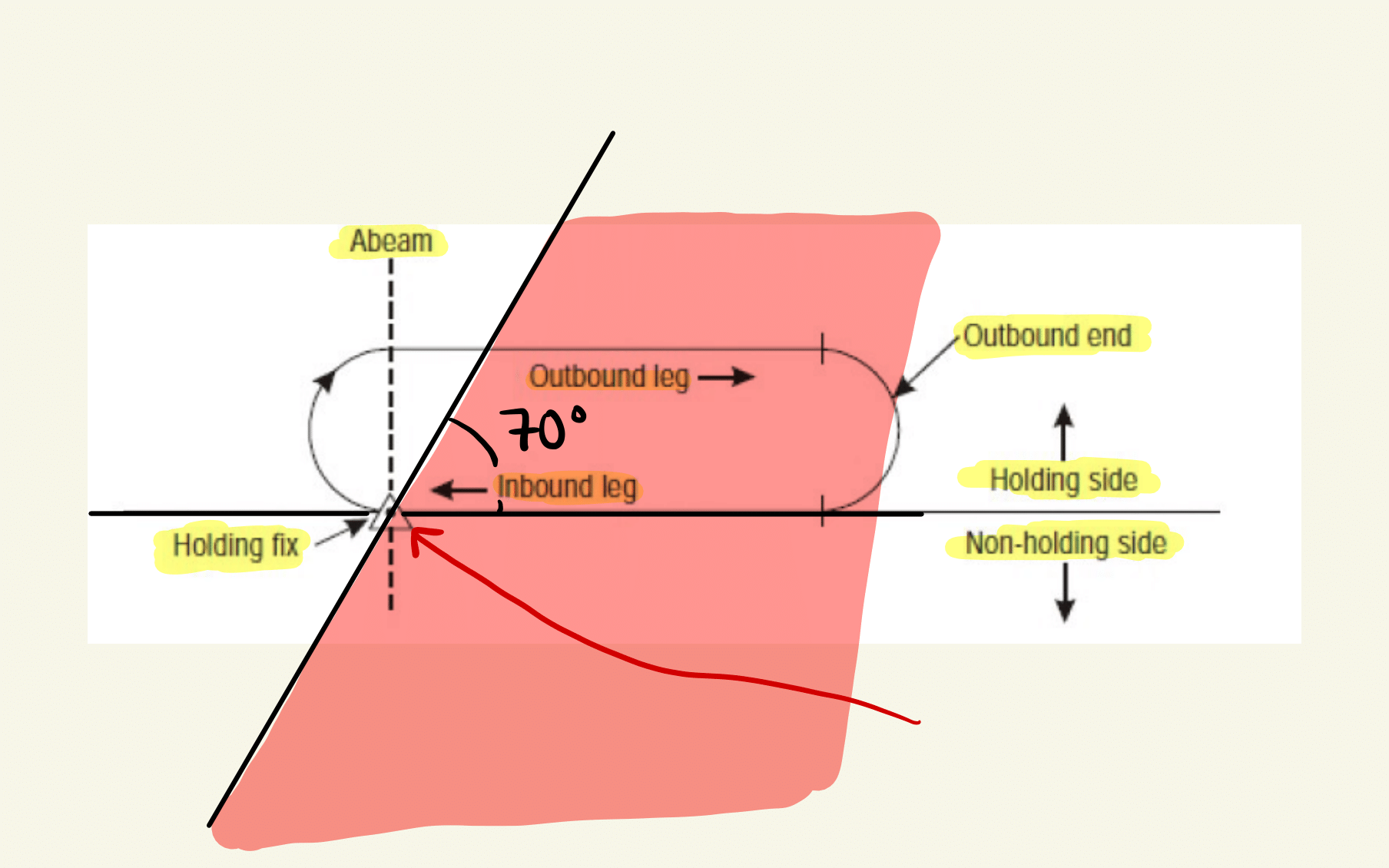
Figure 2.1: Direct holding entry.
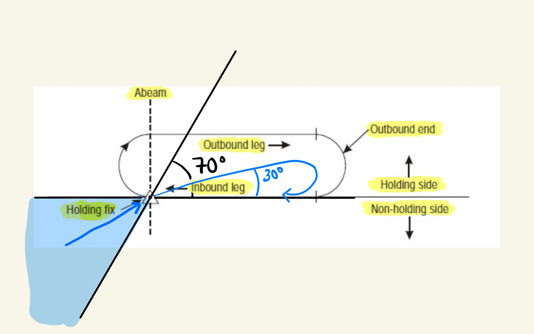
Figure 2.2: Teardrop holding entry.
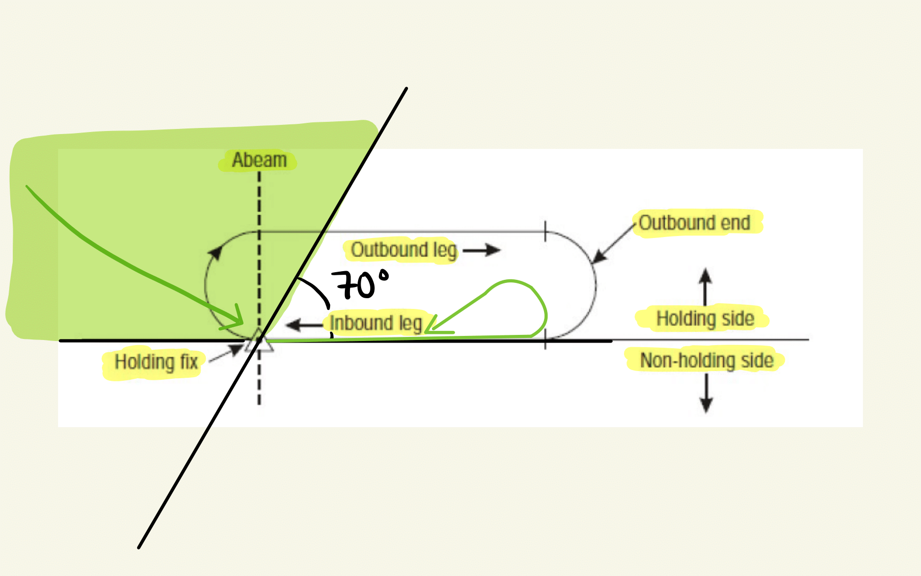
Figure 2.3: Parallel holding entry.
Memory rule: The name of the holding procedure describes the flight path after the holding fix.
Minimum permissible holding height: 300 m obstc. clearance
Shuttle: climb / descend in holding
adapt timing (tail/headwind) and heading (wind correction angle) to maintain the track
2.2.6 Altimeter settings
Add image of Transition level / layer / altitude
Transition altitude not less than 3000 ft AGL
Calculated height of transition altitude rounded up to next full 1000 ft
Calculate transition level from transition altitude (will be passed to aircraft by ATS): TA: 3000 ft, QNH: 990 hPa, (1013 hPa - 990 hPa) * 30 ft/hPa = 660 ft, hence if changing the altimeter reference at 3000 ft to standard pressure would have 3660 ft altitude, hence TL is 4000 ft = FL 40.
Transition altitudes are published in AIPs or SIDs
2.3 Air traffic management
2D separation: horizontal and vertical
Longitudinal separation minima:
- on track: 5 (3) min if proceeding aircraft is 20 kts (40kts) faster
- departure: 3 min if proceeding aircraft is 40 kts faster
- levels crossed: 15 min (default), 10 min (regular fixes), 5 min (absolute minimum)
- on same NDB: more than 30 degrees at distance greater than 15 NM from facility
- same VOR: more than 15 degrees at distance greater than 15 NM from facility
- DME: 20 NM (10NM if 20 kts faster)
clearance to land: at the latest 2 NM from touchdown
no more speed control: 4 NM or less from touchdown
report significant wind changes: - head: 10kts - cross: 5kts - tail: 2 kts
2.4 AIP
GEN: Services, Sigmet, S and R, location indicators, fees, local regulations ENR: communication failures, runway signals, holding/approach/departure procedures AD: fueling, meterological information, runway lightning
2.5 Aeronautical information service AIS
- Movement area: manoeuvring area, aprons, maintenance stands
- apron: load and unload, parking, refueling, maintenance
- airside:
AIRAC: Advanced!
2.5.1 Transponder
- Std Squawk:
- IFR: 2000
- VFR: 7000
- unop: 0000
Transponder failure before dep.: Permission to proceed to nearest suitable airport for repair.
2.5.2 Operations on two parallel runways:
- segregate: one only departures, one only approaches
- semi-mixed: one both, one only one
- mixed: both on both
- progressive: does not exist
2.6 Air Traffic Service ATS
| Class | Type | Separation | Service | Speed Limit | Radio | Clearance |
|---|---|---|---|---|---|---|
| A | IFR | from all | ATC | |||
| B | IFR | from all | ATC | |||
| VFR | from all | ATC | ||||
| C | IFR | from all | ATC | |||
| VFR | from IFR | ATC | yes* | |||
| D | IFR | from IFR | ATC | yes* | ||
| VFR | FIS | yes* | ||||
| E | IFR | from IFR | ATC | yes* | ||
| VFR | FIS | yes* | no | no | ||
| F | IFR | from IFR | FIS | yes* | no | |
| VFR | FIS | yes* | no | no | ||
| G | IFR | FIS | yes* | no | ||
| VFR | FIS | yes* | no | no |
*Speed Limit: Below 10000ft AMSL is 250 kt IAS.
2.7 Aerodroms
2.7.1 Runway
TODA: Take-off distance avaiable (TORA + clearway) TORA: Take-off run available ASDA: Accelerated stop distance available (TORA + stopway) RESA: Runway end safety area (at the end of the runway strip) LDA: Landing distance available
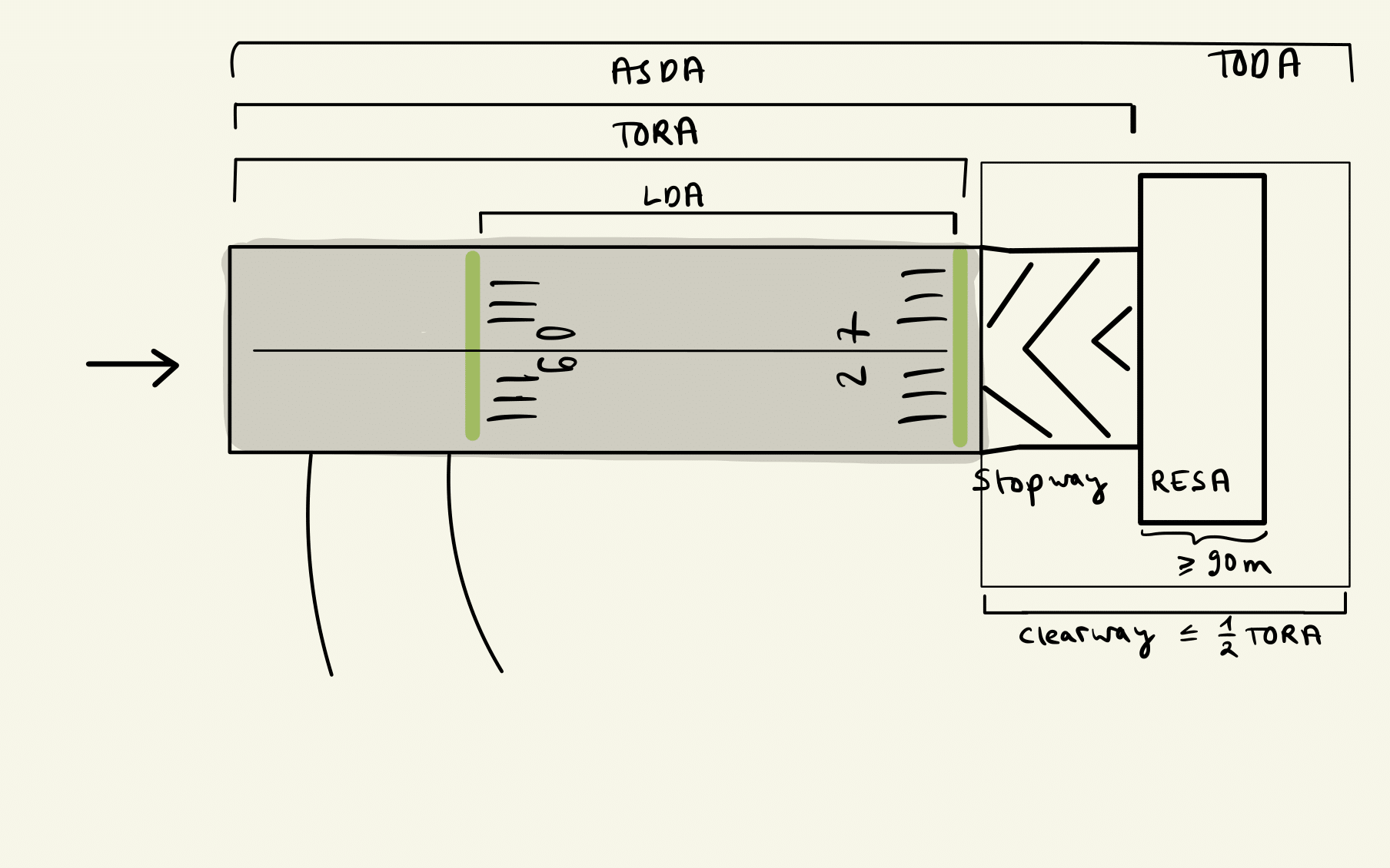
Figure 2.4: Runway zones.
2.7.2 Lightning
Figure 2.5: Runway lights.
2.7.3 Signs
Mandatory instructions: White inscription on red background
C: Visiting pilots should report
Location signs: Yellow writing on black background
2.7.4 Approach aids
PAPI
APAPI
Approach lighting system: Simple (SALS) and precision (PALS)
Number of runway stripes: round up runway width / 4
2.8 Aircraft operations
2.8.1 Departure
Obstacle clearance method for departures with no track guidance:
omni-directional: restricted sectors specified by bearings and distances
straight (< 15 degree deviation from extended runway): track guidance within 20km
turn (> 15 degree): guidance within 10km
Minimum obstacle clearance: 0.8% of horizontal distance in straight departures
Procedure design gradient: 2.5% (at least) + 0,8% (additional margin) = 3,3%
2.8.2 Approach
The approach consists of the following segments:
arrival
initial
intermediate (ends at the FAF/FAP, the FAP is at a maximum (minimum, optimum) of 10 (3, 5) NM from threshold)
final
missed approach, which is separated again in three segments:
initial
intermediate (ends where 50m obstacle clearance is obtained and can be maintained)
final
Figure 2.6: Approach segments.
Optimum glide path 3 degree / 5 percent
MOC: - initial: 300m (1000 ft) - intermediate: 150m (500 ft) - final: 90m (300ft) without FAF and 75m (250ft) with FAF
OCA/H: Obstacle clearance altitude/height DA/H: decision altitude/height = OCA/H + margin MDA/H: for non-precision: Minimum descend A/H = OCA/H + margin
Aircraft categories based on \(V_{AT}\) (IAS at threshold): …
Circling approach.